CNC Turning Centers Guide: Machine Types, Working Principles, Tools, Uses and Benefits
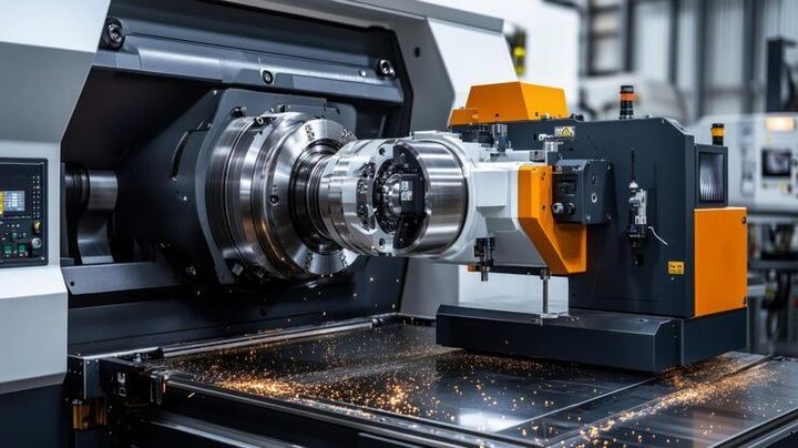
CNC turning centers are computer-controlled machine tools used to shape materials, mainly metals, by rotating a workpiece while cutting tools remove material. CNC stands for Computer Numerical Control, meaning programmed instructions guide the movement of the machine rather than requiring every movement to be controlled manually. A CNC turning center usually combines turning operations with additional functions such as drilling, boring, threading, grooving, and facing.
Context
CNC turning centers are computer-controlled machine tools used to shape materials, mainly metals, by rotating a workpiece while cutting tools remove material. CNC stands for Computer Numerical Control, meaning programmed instructions guide the movement of the machine rather than requiring every movement to be controlled manually. A CNC turning center usually combines turning operations with additional functions such as drilling, boring, threading, grooving, and facing.
The basic idea comes from conventional lathes, which have been used in manufacturing for many years. Traditional lathes depend heavily on an operator to control movement and cutting operations. CNC technology introduced programmable control, allowing the same sequence of movements to be repeated with consistent settings.
Modern CNC turning centers are used in industries such as automotive manufacturing, aerospace, medical equipment, electronics, machinery, and general engineering. Their development is connected with the wider shift toward computer-controlled manufacturing and automated production systems.
Basic Components
A typical CNC turning center contains several important components that work together:
- Spindle: Rotates the workpiece at a selected speed.
- Chuck: Holds the workpiece securely during machining.
- Turret: Holds several cutting tools and positions the required tool for an operation.
- Control panel: Allows programs and machine settings to be entered and monitored.
- Machine bed: Supports the major mechanical components.
- Carriage and slides: Move the cutting tool along programmed axes.
- Coolant system: Helps manage heat and remove chips during suitable machining operations.
Importance
CNC turning centers matter because many manufactured components require controlled dimensions, repeatable shapes, and accurately positioned features. Manual machining can require substantial operator involvement, particularly when a component contains several operations that must be performed in a specific sequence.
Computer-controlled machining can coordinate these movements through programmed instructions. Once a suitable program has been prepared and verified, the machine can follow the defined sequence with limited manual intervention.
This technology also affects everyday products because many components used in vehicles, industrial equipment, appliances, pumps, electrical systems, and other products can be manufactured using turning processes.
Problems Addressed
CNC turning centers can address several common manufacturing challenges:
- Repeating the same machining sequence across multiple components.
- Producing cylindrical or rotationally symmetrical shapes.
- Combining several machining operations in one setup.
- Reducing manual movement between individual operations.
- Maintaining programmed cutting paths and dimensions.
- Supporting complex component designs when the machine configuration permits them.
The actual result depends on machine condition, programming, tooling, workpiece material, measurement methods, and operator practices. CNC technology does not automatically eliminate machining errors, so setup verification and inspection remain important.
Common Machine Types
CNC turning centers are available in different configurations. The appropriate configuration depends on the component geometry and required operations.
| Machine type | General characteristic | Common applications |
|---|---|---|
| Horizontal turning center | Spindle is positioned horizontally | Shafts, bushings, pins, threaded parts |
| Vertical turning center | Workpiece is held vertically | Larger or heavier rotational components |
| Two-axis turning center | Mainly uses X and Z movements | Standard turning operations |
| Live-tool turning center | Includes powered rotating tools | Drilling, milling, and combined operations |
| Twin-spindle turning center | Uses two spindle arrangements | Components requiring work from multiple sides |
| Multi-axis turning center | Provides additional controlled movement | Complex parts and combined machining |
Working Principles
A CNC turning center begins with a digital machining program. The program contains instructions that tell the machine where and how the cutting tool should move, along with information such as spindle rotation, feed movement, tool selection, and machining sequence.
The workpiece is secured in a chuck or another holding arrangement. The spindle rotates the workpiece while the selected cutting tool moves along programmed directions. During turning, material is removed from the outside or inside of the rotating component.
Typical Machining Sequence
A simplified CNC turning process generally follows these stages:
- Component design is prepared using suitable design software.
- Tool paths are planned according to the required geometry.
- CNC program instructions are prepared or generated through CAM software.
- The workpiece is secured in the machine.
- Cutting tools are installed in the turret.
- Tool positions and workpiece coordinates are established.
- The program is checked before machining.
- The machine performs the programmed operations.
- The finished component is measured against the required specifications.
Different machines may use different control systems and programming methods. Operators therefore need to understand the specific machine, tooling arrangement, coordinate system, and program format being used.
Tools and Resources
CNC turning centers use different cutting tools depending on the material and machining operation. Tool geometry, insert material, cutting conditions, and workpiece characteristics all influence machining performance.
Common Cutting Tools
Common tools include turning inserts for removing material from external surfaces, boring tools for enlarging internal holes, threading tools for creating threads, grooving tools for narrow channels, and parting tools for separating a finished component.
Drills may also be installed on machines equipped for powered tooling or suitable drilling operations. Some turning centers can use milling cutters through live tooling, allowing certain milling operations to be performed without moving the component to another machine.
Digital and Reference Resources
Several resources can help readers understand CNC machining:
- BIS Standards Portal: Provides access to Indian Standards and related standard information.
- CNC machine manuals: Explain machine-specific controls, operating procedures, and specifications.
- CAD software: Used to create digital component designs.
- CAM software: Converts design information into machining tool paths and programs.
- Tool manufacturers' technical catalogs: Provide information about inserts, tool geometry, and machining parameters.
- Feeds-and-speeds calculators: Help estimate machining parameters based on material, tool characteristics, and machine conditions.
- Measurement references: Explain methods for checking dimensions, surface characteristics, and geometric accuracy.
The BIS Know Your Standard portal allows users to search Indian Standards by standard number or keyword. BIS also maintains information concerning machine-tool standards and machine safety.
Recent Updates
CNC turning technology continues to develop as manufacturers adopt greater automation, digital monitoring, and integrated machining processes. Current machine designs increasingly combine turning with operations such as drilling and milling, reducing the number of separate setups needed for suitable components.
Another trend is the use of automated measurement and process monitoring. Sensors and probing systems can help detect dimensional changes, tool conditions, or deviations during machining. These technologies can support quality control when correctly configured and interpreted.
Machine-tool development is also increasingly connected with digital manufacturing. Data collection, networked controls, simulation, and production-monitoring systems can provide information about machine operation and machining processes.
India's machine-tool sector has also been influenced by wider manufacturing automation. Recent industry information indicates continued growth in India's machine-tools market, with automation identified as an important factor supporting demand for computer-controlled equipment.
BIS has also continued updating information related to machine-tool standards and safety. Its recent machine-tool documentation covers CNC and NC machine tools, including areas such as geometric and positioning accuracy.
Laws or Policies
In India, CNC turning centers are affected by workplace safety requirements, machinery standards, and product conformity rules. The exact requirements depend on the machine category, workplace conditions, and whether a particular machine falls within a notified regulatory scope.
The Bureau of Indian Standards provides Indian Standards related to machine tools and machine safety. BIS currently lists metal cutting machine tools within its Scheme-X machinery certification framework and provides category-specific guidance for relevant machines.
India's machinery safety framework has also evolved through the Machinery and Electrical Equipment Safety regulatory framework. BIS guidance for metal cutting machines addresses technical documentation, conformity requirements, labeling, and certification-related matters where applicable.
Workplace safety is another important area. The Occupational Safety, Health and Working Conditions Code establishes duties concerning workplace health and safety, including provisions related to machinery and equipment used in factories.
Because regulations and implementation requirements can change, organizations using or manufacturing CNC machinery should refer to current government notifications, applicable Indian Standards, and relevant workplace rules rather than relying only on older documents.
Tools and Resources
Understanding CNC turning centers can be easier when technical information is organized around the main areas of a machining process.
Machine Documentation
Machine manuals provide information about control functions, axes, spindle operation, tool installation, safety systems, alarms, maintenance procedures, and permitted operating conditions. These documents are normally specific to the machine model and control system.
Programming Resources
CNC programming references explain common commands, coordinate systems, tool offsets, spindle instructions, feed movements, and machining cycles. CAM systems can also generate programs from digital component designs.
Measurement Resources
Inspection tools such as vernier calipers, micrometers, dial indicators, bore gauges, and coordinate measuring systems can be used for different dimensional checks. The appropriate measurement method depends on the required tolerance and component geometry.
Safety Resources
BIS publications provide useful background on machine-tool hazards and safety standardization. BIS describes machine tools as equipment that can create mechanical hazards and emphasizes the importance of appropriate safety standards and risk reduction practices.
FAQs
What is a CNC turning center?
A CNC turning center is a computer-controlled machine that rotates a workpiece while cutting tools remove material. Depending on its configuration, it can perform turning, facing, boring, threading, drilling, grooving, and some milling operations.
How does a CNC turning center work?
A CNC turning center follows programmed instructions that control spindle rotation, tool movement, feed movement, and machining sequences. The workpiece rotates while the selected tool follows the programmed path.
What are the main CNC turning center machine types?
Common types include horizontal turning centers, vertical turning centers, two-axis machines, live-tool machines, twin-spindle machines, and multi-axis turning centers. Their capabilities differ according to spindle arrangement, tooling, axes, and control functions.
What tools are used in CNC turning centers?
Typical tools include external turning inserts, boring tools, threading tools, grooving tools, parting tools, drills, and live-tool milling cutters. Tool selection depends on the material, component shape, and machining operation.
Are CNC turning centers covered by Indian safety standards?
Certain metal cutting machine tools fall within India's machinery safety and BIS certification framework. The exact requirements depend on the machine category and applicable regulations, so current BIS information and government notifications should be checked for a specific machine.
Conclusion
CNC turning centers are computer-controlled machine tools designed primarily for machining rotating components. They can combine several operations through programmable movements, different tooling arrangements, and automated controls. Recent developments are increasingly focused on automation, digital monitoring, integrated machining, and machine safety. In India, CNC machine tools are also connected with BIS standards and evolving machinery safety requirements.