Hydraulic Press Complete Guide to Load Types, Components & Uses
A hydraulic press is a machine that uses pressurized fluid to generate force for pressing, forming, bending, shaping, compacting, or assembling materials. Unlike a mechanical press that relies primarily on rotating mechanical components, a hydraulic press transfers force through a hydraulic system containing fluid, a pump, valves, cylinders, and related components.
Context
The basic operating principle is based on Pascal's law. Pressure applied to a confined fluid is transmitted throughout the fluid, allowing a relatively compact hydraulic system to generate substantial force at the press cylinder. The cylinder then moves a ram or platen to apply that force to a workpiece.
Hydraulic presses are used across metalworking, manufacturing, fabrication, plastics processing, composite production, laboratory work, and other industrial applications. Their ability to control pressing force and ram movement makes them suitable for operations that require a controlled load rather than a fixed mechanical stroke.
A hydraulic press can have different configurations depending on its intended application. Common examples include four-column presses, C-frame presses, H-frame presses, horizontal presses, hydraulic forging presses, and specialized forming systems.
How hydraulic force is generated
The hydraulic circuit generally begins with a reservoir containing hydraulic fluid. A pump moves the fluid through valves and into a cylinder, where pressure produces linear movement.
The basic relationship can be represented as:
Force = Pressure × Piston Area
This relationship helps explain why cylinder diameter is important when determining the force that a hydraulic press can generate. Actual machine performance also depends on pressure limits, cylinder design, hydraulic losses, control systems, and the configuration of the press.
Importance
Hydraulic presses are important because many manufacturing processes require controlled compression rather than impact. The ability to regulate pressure and movement allows the same basic machine concept to perform different operations when suitable tooling and process parameters are used.
Hydraulic pressing can be applied to forming sheet metal, compressing materials, assembling components, straightening parts, molding certain materials, and performing laboratory or testing procedures.
Understanding load types
The type of load applied to a workpiece affects how the material behaves and how the press should be configured. Common load arrangements include compression, bending, forming, drawing, and shearing.
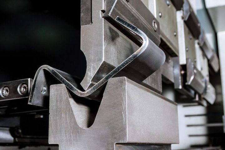
Compression applies force primarily along the material's thickness or length. Bending applies force to change the shape of a component, while forming uses a die to create a specified geometry. Drawing pulls material into a die cavity, while shearing separates material through localized cutting action.
| Load or operation | General purpose | Typical consideration |
|---|---|---|
| Compression | Reduce thickness or compact material | Required force and material response |
| Bending | Change the angle or shape | Material thickness and tooling geometry |
| Forming | Create a defined shape | Die design and material flow |
| Drawing | Form material into a deeper shape | Blank holding and material movement |
| Straightening | Correct unwanted deformation | Part geometry and controlled force |
| Assembly pressing | Join components | Alignment and required insertion force |
Main hydraulic press components
Although designs vary, several components appear frequently in hydraulic press systems.
The frame supports the pressing forces and maintains alignment between the working components. The hydraulic cylinder converts fluid pressure into linear motion. The pump moves hydraulic fluid through the circuit, while valves control direction, pressure, and flow.
Other components can include:
- Hydraulic reservoir
- Electric motor or other prime mover
- Pressure gauge or electronic pressure sensor
- Control system
- Hydraulic hoses or rigid piping
- Ram or moving platen
- Fixed bed or lower platen
- Dies, tooling, or fixtures
- Filters and fluid-conditioning components
- Seals and cylinder components
The exact arrangement depends on the press design and intended operation.
Recent Updates
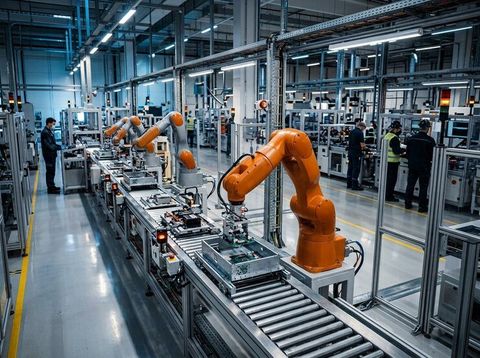
Recent developments in hydraulic press technology have focused on improved control, energy management, automation, monitoring, and integration with manufacturing systems. Modern presses may combine hydraulic power with electronic controls, sensors, programmable systems, and automated material handling.
Electronic monitoring
Sensors can monitor variables such as hydraulic pressure, ram position, temperature, cycle time, and other operating parameters. This information can help operators and maintenance personnel understand how the machine is performing and identify changes that require attention.
Digital controls can also provide more consistent control of pressing sequences. Depending on the machine design, a programmable controller may coordinate pressure, position, speed, dwell time, and return movement.
Energy management
Hydraulic systems can consume energy even when the machine is not performing a pressing operation, depending on their circuit design. Newer systems increasingly use variable-speed pumps, improved hydraulic circuits, and electronic control strategies to reduce unnecessary energy use.
The actual energy requirement varies significantly according to press capacity, cycle characteristics, material, tooling, hydraulic architecture, and production conditions.
Automation and data collection
Hydraulic presses can be integrated into automated production lines. Sensors and control systems can record process information and coordinate the press with material feeding, positioning, inspection, and part handling equipment.
This trend has increased the role of digital monitoring in industrial equipment. However, automation does not remove the need for appropriate machine guarding, inspection, maintenance, and operator training.
Laws or Policies
Hydraulic presses are industrial machines, and their use can be affected by workplace-safety requirements, machinery regulations, technical standards, electrical requirements, and local rules. The applicable requirements depend on the jurisdiction, machine configuration, workplace, and intended application.
Because requirements differ between regions, a general article should not be treated as a legal interpretation or compliance determination. Machine operators and organizations should refer to the rules applicable to their specific location and equipment.
Technical safety standards
International and national standards may address hydraulic press design, safeguarding, controls, risk reduction, and related machine characteristics. ANSI B11.2, for example, is identified by OSHA as a consensus standard concerning hydraulic and pneumatic power presses. OSHA also notes that consensus standards such as ANSI B11 series standards are guidance from their originating organizations rather than OSHA regulations themselves.
A particularly important safety concept is protection around the point of operation. OSHA's hydraulic-press guidance identifies the pressing area as a potential hazard zone and notes the importance of applicable safeguarding.
Hydraulic systems also need appropriate pressure ratings. OSHA's mechanical power press regulation, while specifically addressing mechanical power presses, states that hydraulic equipment within such systems must not exceed the safe working pressure rating of its components.
These references illustrate why hydraulic press operation should be considered together with machine design, guarding, controls, maintenance, and workplace procedures rather than focusing only on the rated pressing force.
Tools and Resources
Several technical resources can help readers understand hydraulic presses and their operating principles.
Force calculations
A hydraulic press force calculator can use the relationship between hydraulic pressure and piston area to estimate theoretical cylinder force. A basic calculation uses:
F = P × A
where F represents force, P represents hydraulic pressure, and A represents piston area.
For example, increasing piston area increases theoretical force at the same pressure. Real machines require additional engineering considerations because friction, pressure losses, component limits, tooling geometry, and machine structure affect actual operation.
Hydraulic circuit diagrams
Hydraulic circuit diagrams show how pumps, reservoirs, valves, cylinders, filters, pressure controls, and other components interact. They are useful for understanding the movement and control of hydraulic fluid.
Manufacturer documentation
Technical manuals and machine documentation can provide information about operating limits, hydraulic specifications, component identification, inspection procedures, and control functions. The documentation applicable to the specific machine should take precedence over generalized information.
Maintenance records
A structured maintenance record can contain:
- Inspection date
- Hydraulic pressure observations
- Fluid condition
- Hose and fitting observations
- Cylinder condition
- Leakage observations
- Guarding checks
- Control-system observations
- Corrective work performed
Such records can help establish a history of machine condition and maintenance activities.
FAQs
What is a hydraulic press?
A hydraulic press is a machine that uses pressurized hydraulic fluid to generate controlled force through a cylinder. It can perform operations such as compression, forming, bending, straightening, and assembly.
What are the main hydraulic press components?
Common hydraulic press components include the frame, hydraulic cylinder, pump, reservoir, valves, hydraulic lines, pressure controls, ram, bed, tooling, and control system. The exact configuration varies according to machine design.
What are the different hydraulic press load types?
Common load types and operations include compression, bending, forming, drawing, straightening, and assembly pressing. Each operation places different demands on the material, tooling, machine structure, and hydraulic system.
How does hydraulic press force work?
Hydraulic force is generated when fluid pressure acts on the area of a hydraulic cylinder piston. The basic relationship is force equal to pressure multiplied by piston area, although practical machine performance depends on additional system and mechanical factors.
What are hydraulic presses used for?
Hydraulic presses can be used for metal forming, bending, straightening, molding, compacting, component assembly, and other controlled pressing operations. The appropriate application depends on the machine configuration, tooling, material, and process requirements.
Conclusion
A hydraulic press uses pressurized fluid and a hydraulic cylinder to generate controlled mechanical force. Its major components include the frame, cylinder, pump, valves, reservoir, controls, ram, bed, and tooling, while different load types support different manufacturing operations. Recent developments have emphasized electronic monitoring, improved hydraulic control, energy management, and automation. Safe application also depends on appropriate machine design, safeguarding, pressure limits, maintenance, and compliance with the requirements applicable to the specific workplace and jurisdiction.