Industrial Gear Guide: Gear Types, Transmission Systems, Uses and Performance Factors
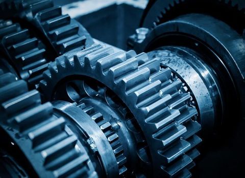
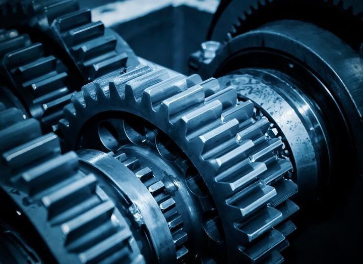
An Industrial Gear Guide explains how gears transfer motion and power between rotating machine parts. Gears are mechanical components with teeth that engage with other gears or toothed elements to change rotational speed, torque, direction, or movement. They have been used in mechanical devices for centuries, from traditional clocks and water-powered machinery to modern industrial equipment, vehicles, and automated production systems.
Context
An Industrial Gear Guide explains how gears transfer motion and power between rotating machine parts. Gears are mechanical components with teeth that engage with other gears or toothed elements to change rotational speed, torque, direction, or movement. They have been used in mechanical devices for centuries, from traditional clocks and water-powered machinery to modern industrial equipment, vehicles, and automated production systems.
Industrial gears are important components in gearboxes, transmission systems, motors, conveyors, pumps, cranes, and manufacturing machines. Their design depends on the movement required, the forces involved, the operating environment, and the relationship between speed and torque. Understanding gear types, transmission systems, applications, and performance factors helps explain how industrial machines operate.
How Industrial Gears Work
A gear transfers motion through contact between its teeth and those of another gear or compatible component. When two external gears mesh, they generally rotate in opposite directions. The relative number of teeth determines their rotational speed relationship.
A smaller driving gear connected to a larger driven gear usually reduces output speed while increasing torque, apart from losses within the transmission. Conversely, a larger driving gear turning a smaller driven gear increases output speed while reducing torque. These relationships allow machinery to perform tasks that require controlled movement or substantial turning force.
Main Types of Industrial Gears
Industrial gear designs differ according to shaft arrangement, load requirements, noise levels, and available space.
Spur gears: Have straight teeth parallel to the shaft axis. They are commonly used in simple speed-reduction systems with parallel shafts.
Helical gears: Have angled teeth that engage progressively. They generally operate more smoothly than comparable spur gears but create axial forces that must be managed.
Bevel gears: Transfer rotation between intersecting shafts, often arranged at right angles.
Worm gears: Use a screw-like worm to drive a toothed wheel. They can provide substantial speed reduction in a compact arrangement, although efficiency depends on their design and operating conditions.
Planetary gears: Use central sun gears, surrounding planet gears, and a ring gear. Their compact layout can distribute loads across multiple gear contacts.
Rack-and-pinion systems: Combine a circular gear with a straight toothed rack to convert rotational movement into linear movement, or the reverse.
Each type serves different mechanical requirements. Selection depends on the intended movement, available space, expected load, and operating conditions.
Importance
Industrial gears help machines operate at suitable speeds and deliver the torque required for specific tasks. Without appropriate transmission arrangements, an electric motor may rotate too quickly or provide insufficient turning force for the connected equipment. Gear systems allow machinery to adapt the motor's output to the needs of the application.
Their performance also affects energy use, machine accuracy, operating noise, maintenance schedules, and equipment life. Manufacturing plants, transport systems, warehouses, construction operations, and processing facilities rely on gear-driven equipment for routine activities.
Industrial Gear Applications
Industrial gears are used across many sectors because different machines require controlled rotation, movement, and force.
Manufacturing: Gearboxes drive conveyors, mixers, machine tools, packaging equipment, and production lines.
Material handling: Cranes, hoists, elevators, and lifting equipment use gear reductions to manage movement and load requirements.
Construction equipment: Excavators, mobile cranes, and other heavy machinery use gears in drive systems, swing mechanisms, and related assemblies.
Energy production: Wind turbines use gearboxes in some designs to adjust rotor speed for generator operation, while other turbine designs use direct-drive systems.
Automotive and transport: Transmission systems use gears to adapt engine or motor output to changing driving conditions.
Food and process industries: Gear-driven mixers, pumps, and conveyors support the movement and processing of materials.
The same gear type can appear in different industries, but its dimensions, materials, lubrication, and supporting components may vary considerably.
Understanding Gear Ratios and Torque
The gear ratio describes the relationship between the rotational speeds of connected gears. For a simple pair of gears, the ratio can be calculated by dividing the number of teeth on the driven gear by the number of teeth on the driving gear.
For example, a 20-tooth driving gear connected to a 60-tooth driven gear produces a 3:1 reduction. Ideally, the output rotates at one-third of the input speed, while output torque increases approximately threefold. Actual torque is lower than this ideal value because of friction and other transmission losses.
| Gear arrangement | General effect | Common application |
|---|---|---|
| Small driving gear to large driven gear | Lower speed, higher torque | Conveyor drives |
| Large driving gear to small driven gear | Higher speed, lower torque | Speed-increasing mechanisms |
| Bevel gear pair | Changes shaft direction | Right-angle drives |
| Worm gear arrangement | Substantial speed reduction | Compact positioning equipment |
| Planetary gearbox | Compact reduction and load distribution | Industrial drives and robotics |
| Rack and pinion | Converts rotation and linear movement | Positioning systems |
The table describes general behavior. Actual performance depends on gear geometry, the number of stages, efficiency, load, and the surrounding transmission design.
Recent Updates
Industrial gear technology continues to develop alongside automation, energy-efficiency initiatives, digital monitoring, and advanced manufacturing. Across 2024–2026, important industry directions include condition monitoring, precision gear production, improved materials, and the integration of gearboxes with electronically controlled motors. Adoption varies by sector, equipment age, and operating requirements.
Smart Monitoring and Predictive Maintenance
Sensors can measure vibration, temperature, rotational speed, and other operating conditions in gear-driven equipment. Monitoring systems analyze these readings to identify changes that may indicate misalignment, lubrication problems, tooth damage, or bearing wear.
Some facilities use condition-monitoring software to identify developing faults before they cause an unplanned shutdown. However, sensor readings require suitable interpretation, and not every fault can be predicted accurately. Inspection and maintenance procedures remain important even when digital monitoring is available.
Precision Manufacturing and Energy Efficiency
Computer-controlled machining, improved tooth grinding, and digital inspection methods help manufacturers control gear dimensions and surface quality. More precise manufacturing can support smoother engagement, reduced vibration, and consistent transmission performance when the complete assembly is properly designed.
Material development and surface treatments also influence resistance to wear, fatigue, and contact damage. Meanwhile, industrial operators are paying greater attention to transmission efficiency because losses in gearboxes can increase energy demand during continuous operation. Efficiency depends on gear geometry, lubrication, alignment, operating temperature, and the number of transmission stages.
Integration With Industrial Automation
Modern automated production lines often combine gearboxes with electric motors, variable-frequency drives, sensors, and programmable controllers. These systems allow machinery to adjust speed and movement according to production requirements.
Robotics and automated handling equipment also rely on compact, accurately controlled transmissions. In such applications, backlash, stiffness, repeatability, and load capacity may be particularly important because small mechanical errors can affect positioning accuracy.
Laws or Policies
Industrial gear manufacturing, installation, and operation are affected by machinery safety rules, workplace regulations, environmental requirements, and technical standards. The exact requirements depend on the equipment, industry, intended use, and country where the machinery operates.
Industrial Machinery Regulations in India
In India, industrial machinery may be subject to applicable occupational safety requirements, factory regulations, electrical safety provisions, and environmental rules. The Occupational Safety, Health and Working Conditions Code, 2020, forms part of the country's labour-law framework, while its practical application depends on commencement notifications, relevant rules, and the circumstances of the workplace.
Factories and industrial operators must consider applicable requirements for machine guarding, safe operation, maintenance, and worker protection. Rotating shafts, exposed gear teeth, and moving transmission components can create entanglement, crushing, and impact hazards. Guards and isolation procedures help reduce these risks when appropriately designed and implemented.
Technical Standards and Equipment Safety
The International Organization for Standardization (ISO) publishes standards covering gear accuracy, terminology, load capacity, and related engineering subjects. ISO 6336, for example, addresses the calculation of load capacity for cylindrical involute gears. Other standards may apply to specific gear types, measurement procedures, or equipment categories.
Standards are not automatically legal requirements in every situation. Their relevance depends on contractual specifications, applicable regulations, industry practices, and whether a particular standard has been adopted or referenced by an authority.
Industrial facilities should also consider lubrication handling, waste management, noise exposure, and electrical safety where applicable. The appropriate requirements should be determined from the machinery's documentation and the rules relevant to its location and use.
Tools and Resources
Several technical resources help engineers, maintenance teams, students, and equipment operators understand industrial gears and transmission systems. Their usefulness depends on the gear arrangement and the level of detail required.
Gear Calculators and Engineering Software
Gear ratio calculators determine relationships between input and output speeds based on gear tooth counts. Torque and power calculators help estimate operating requirements, while engineering software can model gear geometry, contact forces, vibration, and transmission behavior.
Computer-aided design (CAD) applications are used to create gear models and check how components fit within a machine assembly. More advanced engineering tools can support gear tooth design, strength analysis, and manufacturing preparation. Calculations should use suitable assumptions and verified equipment specifications.
Standards and Technical Documentation
ISO publications provide technical references for gear terminology, accuracy, and load calculations. Manufacturer manuals and engineering data sheets describe gearbox ratings, lubrication requirements, allowable loads, operating temperatures, and maintenance intervals.
Technical documentation is especially important when replacing a gearbox or changing a gear arrangement. Similar-looking units may differ in shaft dimensions, mounting configuration, reduction ratio, and permissible input power.
Inspection and Maintenance Tools
Maintenance teams may use vibration analyzers, infrared temperature instruments, lubricant analysis, alignment tools, and visual inspection equipment to assess gear-driven machinery. These methods can help identify unusual operating conditions, although individual measurements do not always establish the precise cause of a fault.
Routine maintenance records can include operating hours, lubricant changes, measured vibration, temperature readings, inspection findings, and corrective work. Consistent records help maintenance personnel compare equipment behavior over time.
FAQs
What are the main types of industrial gears?
The main types include spur, helical, bevel, worm, and planetary gears, as well as rack-and-pinion systems. Each design supports different shaft arrangements, speed relationships, and movement requirements.
How does an industrial gear transmission system work?
A gear transmission transfers rotation between connected components and changes speed, torque, or direction. The gear ratio determines the theoretical speed relationship, while friction and other losses influence actual output performance.
What factors affect industrial gear performance?
Important factors include gear geometry, material strength, tooth accuracy, lubrication, alignment, operating temperature, vibration, and applied load. Maintenance and installation quality also affect reliability.
Which industrial gears are used for high torque?
Large reduction gearboxes, planetary arrangements, and some worm gear systems can provide high output torque, depending on their design and ratings. The appropriate configuration depends on the required speed, load, duty cycle, and efficiency.
How are industrial gearboxes maintained?
Maintenance commonly involves checking lubrication, inspecting for wear or damage, monitoring vibration and temperature, and verifying alignment. Inspection intervals and procedures should follow the equipment manufacturer's documentation and applicable safety requirements.
Conclusion
Industrial gears transfer motion and power while adjusting speed, torque, direction, or movement to suit machinery requirements. Spur, helical, bevel, worm, planetary, and rack-and-pinion systems each have distinct operating characteristics. Digital monitoring, precision manufacturing, and automation are influencing how gear-driven equipment is designed and maintained. Gear performance depends on correct selection, installation, lubrication, operating conditions, and compliance with relevant safety requirements.