Industrial 3D Scanners Guide: Scanning Methods, Accuracy, Applications and Selection Considerations
Industrial 3D scanners are measurement systems that capture the shape and dimensions of physical objects and convert them into digital three-dimensional data. An Industrial 3D Scanners Guide is useful for understanding how these systems work, what scanning methods are available, how accuracy is evaluated, and where the technology is used.
Context
Industrial 3D scanners are measurement systems that capture the shape and dimensions of physical objects and convert them into digital three-dimensional data. An Industrial 3D Scanners Guide is useful for understanding how these systems work, what scanning methods are available, how accuracy is evaluated, and where the technology is used.
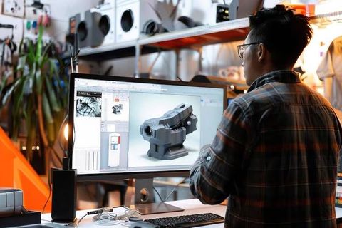
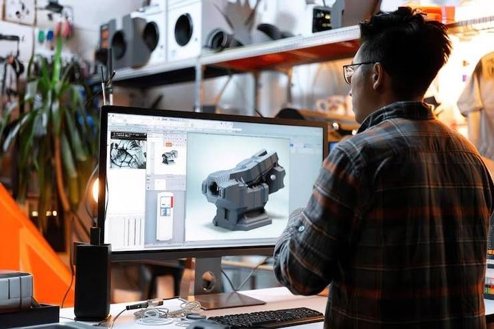
Unlike traditional measurement methods that may record individual dimensions, 3D scanning can capture large areas of an object as a point cloud or polygon mesh. The resulting data can then be compared with computer-aided design (CAD) models, inspected for dimensional differences, or used for digital documentation and reverse engineering.
How Industrial 3D Scanning Developed
Industrial 3D scanning developed from advances in optical measurement, computer vision, laser technology, and digital modeling. Earlier measurement systems often depended heavily on physical contact between a probe and an object. Optical scanning introduced another approach by collecting surface information without requiring direct contact.
Several scanning methods are now used in manufacturing environments. These include laser triangulation, structured-light scanning, photogrammetry, and other optical approaches. The appropriate method depends on the object's size, surface characteristics, required accuracy, environment, and intended application.
What a 3D Scanner Captures
A scanner records geometric information from the visible surface of an object. Multiple scans can be combined to create a more complete representation.
The main digital outputs can include:
- Point clouds containing measured points in three-dimensional space
- Polygon meshes representing the object's surface
- Color deviation maps for comparing measured and reference geometry
- CAD-related data for design and engineering workflows
- Inspection reports showing dimensional differences
The scanning process generally involves capturing individual views, aligning those views, processing the collected data, and creating a usable digital model.
Importance
Industrial 3D scanning matters because manufacturers and engineers often need detailed information about physical parts, tools, assemblies, and structures. A digital representation can make it easier to examine geometry that may be difficult to describe using only conventional measurements.
The technology is used across automotive manufacturing, aerospace, machinery, construction, energy, medical-device production, research, and product development. It can also support maintenance and inspection activities where the existing physical condition needs to be documented.
Problems Addressed by 3D Scanning
One common challenge is measuring objects with complex curves, irregular surfaces, holes, or free-form shapes. Traditional instruments can measure selected points, while an optical 3D system can capture a larger portion of the surface during a scanning sequence.
Another challenge involves comparing a manufactured object with its intended design. Scan data can be aligned with a CAD model to identify areas where the physical part differs from the reference geometry.
3D scanning can also help with reverse engineering. When original drawings or CAD files are unavailable, measurements from an existing component can provide geometric information for creating a digital reference.
Accuracy and Measurement Conditions
Accuracy is not determined only by the scanner itself. Results can also be affected by surface color, gloss, ambient lighting, temperature, vibration, scanning distance, object movement, alignment methods, and data-processing procedures.
ISO 10360-13:2021 describes acceptance and reverification testing for optical 3D coordinate measuring systems. It addresses verification of measuring performance under specified surface conditions and provides a framework for evaluating optical measurement performance.
For this reason, published accuracy specifications should be considered together with the actual measurement environment and the procedure used during scanning.
Common Scanning Methods
Different scanning principles suit different industrial situations.
| Scanning method | Basic principle | Common applications | Important consideration |
|---|---|---|---|
| Laser scanning | Laser light measures surface geometry | Parts, tools, machinery | Surface and lighting conditions |
| Structured light | Projected patterns capture surface shape | Inspection, modeling, small and medium parts | Controlled lighting can help |
| Photogrammetry | Multiple photographs calculate spatial relationships | Large objects and structures | Image quality and reference points |
| Laser tracker scanning | Laser-based spatial measurement | Large industrial assemblies | Setup and measurement volume |
| Handheld optical scanning | Portable optical capture | Field inspection and reverse engineering | Operator technique and tracking |
No single method is appropriate for every object. Large structures may require a different measurement approach from small precision components, while dark, reflective, transparent, or highly textured surfaces may require additional preparation or scanning techniques.
Recent Updates
From 2024 through 2026, industrial 3D scanning has continued moving toward portable measurement, digital inspection, scan-to-CAD workflows, and integration with wider manufacturing systems. Recent industry discussions emphasize the use of scanning closer to production areas rather than limiting measurement activities to dedicated laboratories.
Portable Scanning
Portable systems have become increasingly relevant for components that are too large or inconvenient to move to a fixed measurement area. Handheld and mobile systems can capture components directly on the production floor or in maintenance environments.
The trend is connected with shorter production cycles, distributed manufacturing, and the need to inspect physical geometry within the same working environment where manufacturing activities take place.
Scan-to-CAD and Digital Workflows
Another development is stronger integration between scan data and engineering software. Instead of treating a scan as an isolated visual model, current workflows increasingly connect measured geometry with CAD comparison, dimensional inspection, reverse engineering, and digital manufacturing processes.
Industrial software can transform point clouds into meshes, compare scans against reference models, and generate deviation information. The broader trend is toward connecting measurement data with digital engineering and production systems.
Automation and Intelligent Processing
Automated alignment, surface recognition, data filtering, and guided scanning are also becoming more common. These functions can reduce repetitive manual processing and help standardize measurement workflows.
Artificial intelligence and computer-vision techniques are being explored in areas such as feature recognition, automated inspection, and data interpretation. Their usefulness still depends on measurement quality, software validation, and the specific industrial application.
Laws or Policies
In India, industrial 3D scanning is generally influenced by technical standards, measurement practices, sector-specific requirements, and quality-management procedures rather than by one single law specifically governing all 3D scanners.
Indian Standards and Metrology
The Bureau of Indian Standards (BIS) provides a searchable standards system through its “Know Your Standard” platform. The database allows users to search Indian Standards by standard number or keyword and review associated information.
India also maintains standards related to geometrical product specifications and coordinate measurement. For example, BIS documentation lists IS 15635 (Part 5):2024 as aligned with ISO 10360-5:2020 for acceptance and reverification testing of coordinate measuring systems using contacting probing systems.
For optical 3D measurement, ISO 10360-13:2021 provides a relevant international reference for acceptance and reverification testing of optical 3D coordinate measuring systems.
Sector-Specific Requirements
Manufacturers may also need to follow standards or contractual measurement requirements applicable to their industry. Automotive, aerospace, medical-device, engineering, and other regulated sectors can have additional quality, traceability, documentation, or inspection requirements.
The applicable requirement depends on the product, measurement purpose, industry, and organization involved. Therefore, general information about 3D scanning should not be treated as a substitute for checking the specific standards applicable to a particular manufacturing activity.
Tools and Resources
Several types of tools can help readers understand and use industrial 3D scanning technology.
Standards Databases
The BIS standards portal is useful for checking Indian Standards by keyword or standard number. It can help users identify relevant documents related to engineering measurement, geometrical specifications, and other manufacturing subjects.
The ISO website provides information about international standards, including ISO 10360 documents covering coordinate measuring systems and optical 3D measurement.
CAD and Inspection Software
CAD software can be used to compare scanned geometry with reference models or develop digital representations of physical components. Inspection platforms can calculate dimensional deviations, create color maps, and organize measurement results.
Common data formats can include point-cloud, mesh, and CAD-related files. Compatibility should be checked before beginning a scanning workflow because different applications can support different file types and processing functions.
Measurement Planning Templates
A basic scanning plan can record:
- Object dimensions and surface characteristics
- Required measurement accuracy
- Scanner type and scanning method
- Environmental conditions
- Reference markers or alignment method
- Number of scan positions
- Data-processing procedure
- Inspection criteria
- Final output format
Planning these elements before scanning can make the measurement process easier to document and repeat.
FAQs
What are industrial 3D scanners used for?
Industrial 3D scanners are used to capture physical geometry for inspection, reverse engineering, CAD comparison, dimensional analysis, documentation, and manufacturing research. Applications vary according to scanner type and measurement requirements.
Which 3D scanning method is suitable for industrial inspection?
The appropriate method depends on object size, surface properties, required accuracy, measurement environment, and inspection purpose. Laser and structured-light systems are commonly used for detailed surface measurement, while other approaches can be appropriate for large objects.
How accurate are industrial 3D scanners?
Accuracy varies by scanner, measurement volume, calibration, surface condition, environment, and scanning procedure. ISO 10360-13:2021 provides a framework for acceptance and reverification testing of optical 3D coordinate measuring systems.
Can industrial 3D scanners create CAD models?
Scanners primarily capture measured surface data rather than automatically creating a complete engineering design. Specialized software can process point clouds and meshes and assist with scan-to-CAD or reverse-engineering workflows.
What should be considered when selecting an industrial 3D scanner?
Important considerations include object size, required accuracy, surface characteristics, scanning range, portability, tracking method, data formats, software compatibility, environmental conditions, and the type of inspection or modeling required.
Conclusion
Industrial 3D scanners provide a way to capture physical geometry as digital three-dimensional data for measurement, inspection, documentation, and engineering workflows. Different scanning methods have different strengths, and accuracy depends on both the equipment and the measurement conditions. Recent developments have emphasized portable scanning, scan-to-CAD integration, automated processing, and connected digital workflows. In India, relevant technical standards from BIS and international references such as ISO 10360 can provide useful guidance for measurement and verification practices.